
From Cardboard to CAD: Designing Paikea’s Shower Sump and Drain
Every finished part on this boat starts somewhere unglamorous. This one started as cardboard.
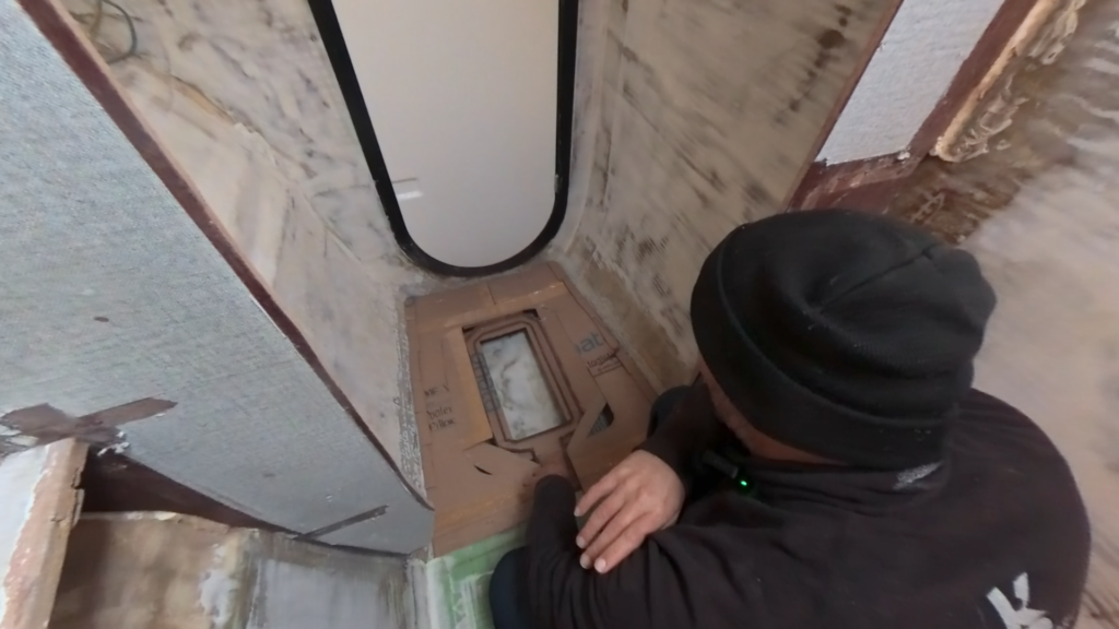
Before any of the actual bathroom floor took real shape, the design existed as a rough cardboard mock-up — cheap, fast, and disposable enough to get wrong a few times before committing to anything permanent. From there, the same shape got rebuilt properly in CAD, with real dimensions, real tolerances, and the kind of precision cardboard simply can’t offer once the geometry gets complicated.
Why this floor needed so much thought
A shower floor sounds simple until you actually have to make water go somewhere specific, reliably, on a boat that heels, pitches, and occasionally sits on a slight list. This one needed to shed water toward a single low point regardless of which way the boat happened to be leaning at the time.
The floor itself is 20mm foam at its thickest, tapering down to nothing at the drainage valley — a deliberate fall built into the shape itself, not an afterthought bolted on top. At the front and back edges, wedge-shaped sections encourage water inward from both directions rather than letting it pool at the extremities. Even with that geometry doing most of the work, a small amount of corner pooling on a list is unavoidable — the fix for that isn’t more foam shaping, it’s extra fairing compound worked deliberately into the corners during the finishing stage, subtly nudging water toward the drain rather than leaving it to sit.
Designing a hatch that won’t wear out its own seal
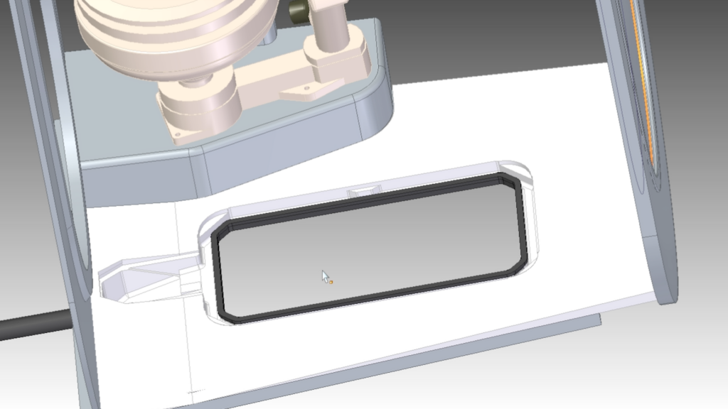
The hatch covering the sump access needed to solve a problem that’s easy to get wrong: a seal that’s compressed too hard wears out fast, sometimes cutting itself on the first few closures. The fix is a series of small support flats and steps built directly into the floor’s geometry — physical stops that limit exactly how far the hatch can compress the seal before it bottoms out on solid support instead of squeezing the seal indefinitely. The seal’s sealing blade presses into the foam itself, with foam carried up the edge of the hatch opening to increase the total sealing surface area — more contact, less pressure on any single point, a genuinely watertight result without relying on brute compression to get there.
Water flow details got the same level of attention. Ramped corners keep water moving through rather than pooling and turning stagnant. Flow channels carry water across corners rather than letting it collect. One small flat section does allow limited pooling, but it’s minor enough not to matter in practice — a rare case of accepting a small imperfection rather than over-engineering a fix for something inconsequential.
The sump and drain
Water leaving the sump runs through a carbon fibre tube — consistent with the boat’s black-means-carbon-and-epoxy standard running throughout the refit. The sump itself sits deliberately low and deep, generating a small amount of head pressure that helps push water through the pipe rather than relying purely on gravity and hoping for the best. A steep internal fall keeps soap scum from building up rather than settling and hardening inside the sump over time.
A stepped ledge inside the sump holds a stainless steel mesh strainer across the water’s path — catching hair and debris before it can reach the pump. A small drop-off beneath that step keeps the strainer sitting slightly proud rather than flush, so buildup accumulates against the mesh itself rather than packing solid underneath it where it’s harder to clean out.
Two separate hatch-retention systems are planned. The primary is a simple bungee arrangement, the same low-tech, reliable method used on lightweight dinghies — a cord tensioned between the floor and the underside of the hatch, holding it down under spring pressure alone. A mechanical backup exists too: a hook on the hatch engaging a fixed point, secured with a wing-nut fitting through a fiberglass mounting plate, in case the bungee system alone doesn’t hold up in practice.
Where the toilet actually goes, and why
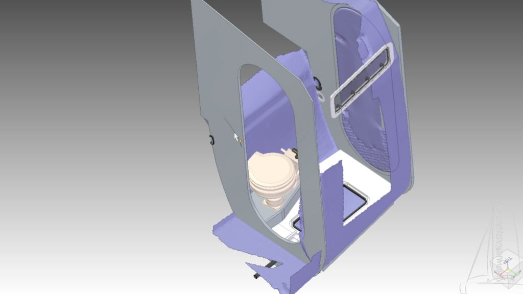
Fitting a toilet into this space wasn’t a simple matter of finding an empty corner. The aft corners were ruled out immediately — the boat narrows too much back there, and encroaching on the engine room door access was never an option, given how frequently that door gets opened to check fluids, temperatures, and general system health. With the boat’s overall interior philosophy keeping everything inboard — cupboards, shelving, systems all routed internally, leaving outboard walls clean and open — the toilet’s position followed that same logic: inboard and forward, in the space that actually made sense once the aft corners and outboard walls were both off the table.
That placement created its own plumbing challenge: routing both the toilet water inlet and the shower drain outlet through the same bulkhead penetration, side by side, with an upstand built in at the exit point specifically to stop water tracking down into the bilge rather than continuing along its intended path.
Verifying it all actually fits: 3D scanning
Rough dimensions, built up from repeatedly measuring the boat by hand, get you close — but “close” isn’t good enough when a toilet, its plumbing, and a custom-shaped bulkhead all need to occupy the same space without clashing. That’s where 3D scanning came in: not scanning the entire boat, which would demand computing power and storage well beyond what’s practical for a project like this, but scanning the specific section in question to confirm the model actually matched reality.
It mostly did. The engine room door lined up closely with the CAD model. Some areas were slightly off — the hull bulged out marginally more than expected in one spot, and a chamfer panel that had been essentially guessed at turned out to be wrong entirely. But in the areas that actually mattered — where the toilet and its plumbing needed to sit — the scan confirmed the design worked, with no unexpected clashes between the modeled parts and the real boat.
From model to mould
The final CAD geometry became the basis for a 3D-printed mould, split into sections small enough to fit the printer’s build plate and printed across multiple separate sessions. A mid-print filament shortage forced a material switch partway through — from PETG to PLA — leaving a visibly different-coloured section in the finished tooling. Cosmetically inconsistent, functionally irrelevant, and a reminder that even carefully planned fabrication runs into small real-world hiccups. The print settings themselves — a high wall count with moderate infill — reflect lessons learned over multiple projects about what actually holds up to vacuum loading when used as an infusion tool.
The part of the process nobody sees
None of this — the fall in the floor, the hatch steps, the sump geometry, the toilet’s exact position — happened by guesswork or improvisation on the day. Every dimension traces back through cardboard mock-ups, CAD modelling, and 3D scan verification before a single piece of foam got shaped for real. When a finished part shows up looking simple in a video, that simplicity is usually the result of a lot of unglamorous design work nobody ever sees.
More on Floors and Hatch Design
Interested to see more on our approach to hatch design and build? Read Paikea’s Composite Hatches: The Full Story More on the story of creating and installing lightweight composite floors on our Paikea’s Refit page.
More on our floor rebuild in Paikea’s Floors: Replacing Timber with Structural Composite.