Author: Shayne and Anna
Key Message: The most important part of a structural refit is understanding and optimizing load paths. By relocating a bulkhead to align with the strongest part of the daggerboard foil, we significantly increase Paikea’s structural integrity and sailing performance.
Introduction: Identifying a Structural Flaw
During Paikea’s refit, we noticed a discrepancy. On one side of the daggerboard case, a single bulkhead connected to a main stringer. On the other side, two smaller bulkheads were placed off-center. This wasn’t just an asymmetry; it was a fundamental flaw in how loads from the daggerboard were transferred into the hull.
Our solution was to replace the two poorly located bulkheads with a single, robust one, strategically placed for maximum effect. The process of integrating it seamlessly involved a clever composite technique: the pre-fabricated return flange.
1. The Core Engineering: Why Daggerboard Loads are Not Simple
A daggerboard doesn’t just push straight down. It experiences massive bending moments. Where this bending load is transferred into the hull structure is critical.
- The Strongest Point of a Foil: The thickest part of any aerodynamic foil is at the 30-40% chord point (the distance from the leading to the trailing edge). This is not the halfway point.
- Where the Structure Lives: Inside the daggerboard itself, the primary structural elements (spars, shear webs) are concentrated in this thickest section to handle the highest loads.
- The Original Design Flaw: The two original bulkheads were placed outside of this high-load area. They were essentially “missing” the main structural member of the daggerboard, meaning loads weren’t being efficiently transferred into the hull.
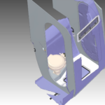
Our new, single bulkhead is positioned precisely to intersect with this 30-40% chord point. It connects directly to a main longitudinal stringer, creating a robust, direct path for daggerboard loads to dissipate into the hull structure.
2. The Composite Solution: A Structural Bulkhead with an Integrated Flange
The new bulkhead is a major component. We vacuum-infused it, creating a incredibly strong and lightweight part weighing just 1.9 kg. But integrating it required a clever detail.
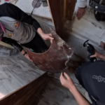
- The Challenge: How do you create a perfect, strong bonding surface for the new floor onto this bulkhead, especially in a tight, inaccessible space?
- The Technique: The Pre-Fabricated Return Flange. Instead of struggling to laminate underneath the floor after installation, we built the bonding interface separately.
- We used a floor template to establish the correct height.
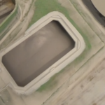
- We molded it perfectly to the daggerboard case using a simple bog-and-release-tape technique.
- We then laminated a sturdy fiberglass flange with a cove onto this jig in the comfort of the workshop.
- The Result: This pre-made “ledge” was then bonded to the new bulkhead. It provides a perfect, ready-to-glue surface for the floor, making the final installation simple and ensuring a structurally integral bond.
3. The Payoff: A Lighter, Stiffer, Safer Hull
This change, while seemingly small, has a profound impact:
- Optimized Load Paths: Daggerboard loads are now efficiently channeled into the hull, reducing stress concentrations.
- Increased Global Stiffness: The hull is now stiffer in a critical area, improving sailing performance.
- Significant Weight Savings: We removed two heavy, inefficient bulkheads and replaced them with one optimized, lightweight composite part, continuing our trend of removing hundreds of kilos from the boat.
Conclusion: It’s All About the “Why”
This project underscores a core principle of our refit: every modification is driven by engineering rationale. We didn’t just add a bulkhead; we solved a load path problem. The return flange wasn’t just a convenience; it was the enabling technique that allowed us to execute the structural upgrade to a professional standard. It’s this combination of smart design and skilled fabrication that transforms a refit.
See More of our Structural Floor Build.
- Solving Boat Shower Drainage with Cardboard, CAD, 3D Scanning & 3D Printing
 The Hybrid Design Workflow: Building a Boat Shower Floor with Cardboard, CAD, and 3D Scanning: Walk through the hybrid design process for a custom boat shower floor. See how cardboard prototyping, CAD, 3D scanning, and 3D printing combine to solve complex drainage and access problems in a marine refit. Author: Shayne and Anna Introduction Designing… Read more: Solving Boat Shower Drainage with Cardboard, CAD, 3D Scanning & 3D Printing
 - The Boat Shower Floor Blueprint: Drainage, Hatches & Avoiding Bilge FloodsWhen your floor needs to drain, provide access, and never flood the bilge. A deep dive into the logic behind our custom shower hatch. Key Topic: Join Shayne & Anna in the bilges for a marine design deep-dive. We’re solving the boat shower’s trickiest puzzle: creating a floor that drains properly, includes mandatory access hatches,… Read more: The Boat Shower Floor Blueprint: Drainage, Hatches & Avoiding Bilge Floods
- Diagnosing and Repairing Hull Delamination and Core Damage.The Problem: From Floor Installation to Structural Repair Author: Shayne and Anna During the installation of new cabin soles in our Catana 42 refit, a routine task uncovered a significant structural issue. The discovery process is a textbook example of why systematic disassembly is critical. Initial Indicators: The Technical Failure:In a cored composite structure (like… Read more: Diagnosing and Repairing Hull Delamination and Core Damage.
- Re-Engineering a Hull: Load Paths, Daggerboards, and a New Structural BulkheadAuthor: Shayne and Anna Key Message: The most important part of a structural refit is understanding and optimizing load paths. By relocating a bulkhead to align with the strongest part of the daggerboard foil, we significantly increase Paikea’s structural integrity and sailing performance. Introduction: Identifying a Structural Flaw During Paikea’s refit, we noticed a discrepancy. On… Read more: Re-Engineering a Hull: Load Paths, Daggerboards, and a New Structural Bulkhead
- Refit Progress: Templating, Infusing, and Building a New Laminating TableKey Message: A major refit is a series of small, repetitive, and precise steps. By creating a family “assembly line” for templating and infusion, we’re efficiently producing lightweight, custom composite floors while constantly improving our workshop tools. Author: Anna & Shayne Introduction: The Flooring Assembly Line The transformation of Paikea’s interior continues, one floor panel at… Read more: Refit Progress: Templating, Infusing, and Building a New Laminating Table