Topic Overview: This post details the professional method for creating a strong, watertight penetration in a fiberglass hull or bulkhead. We cover the laminate rule of thumb, the step-by-step laminating technique using a 3D-printed plug, and the critical design feature that ensures the plug can be removed.
Every hole drilled in a boat is a potential weak point. For through-hulls, wiring conduits, or plumbing lines, a standard hole saw cut is insufficient. It leaves exposed, wicking end-grain and creates a stress concentration. The professional solution is to laminate a sealed, structural passage directly into the composite structure.
This process, demonstrated in our latest video, uses a custom 3D-printed plug to create a perfect, molded-in penetration.
The Golden Rule: Sizing the Laminate
The fundamental principle for a strong penetration is matching the laminate schedule.
The Rule: The total weight of the laminate you build into the penetration hole should equal the weight of the skin you are penetrating.
Example: If your hull is a 600g/m² (gram-per-square-meter) double-bias (DB) layup, you should install approximately 600g/m² of DB laminate into the hole.
Practical Application: Using lighter materials (e.g., 300g/m²) is acceptable, as it makes conforming to complex shapes easier. However, you must then use multiple layers to achieve the required total weight, ensuring the penetration is as strong as the surrounding area.
Step-by-Step: Laminating the Plug
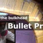
Short video showing the lamination of a 3D printed plug into a structural bulkhead penetration.
Plug Preparation: A 3D-printed plug is the ideal mold. It should be sized to create the final desired internal diameter of the penetration.
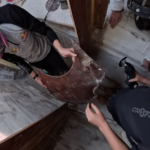
Wetting Out: Laminate is wet out on a table and carefully wrapped around the plug. The key is to ensure the fibers run continuously from the inner flange, through the penetration tube, and onto the outer flange.
Staggering Joints: When applying multiple layers, the location of the material joint is critical. Never stack joints on top of each other. Alternate the joint location from one side of the flat flange to the other. The subsequent layer will bridge and reinforce the joint of the previous one, creating a uniform structure without weak spots.
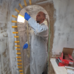
Installation: A high-density, cabosil-thickened resin mix is applied into the prepared hole in the bulkhead or hull. The laminated plug is then “squidged” into place, ensuring the resin fully encapsulates the laminate and eliminates air pockets.
Crucial Design Detail: “Draw” on the Plug
The most common problem in this process is a plug that gets permanently stuck. The solution is to incorporate “draw”—a deliberate taper—into the plug’s design.
What it is: The plug is not a perfect cylinder. It is wider at the base (the flange end) and narrower at the tip, making it slightly wedge-shaped.
Why it matters: This taper ensures that as the plug is pulled out, it clears the laminated part without hanging up on small inconsistencies in the laminate thickness. A parallel-sided plug is far more likely to become seized.
Post-Use: Thermoplastic 3D-printed plugs can be gently warmed with a heat gun to reshape them or adjust their fit, making them reusable for multiple identical penetrations.
Conclusion
This method transforms a potential failure point into a structural, sealed, and professional-grade component. By investing a small amount of time in creating a molded penetration, you eliminate future worries about leaks, delamination, and stress cracks, ensuring the long-term integrity of your vessel.
Implement This Technique: Get the Plug File
Understanding the theory is one thing; having the right tool for the job is another. To make it easy for you to apply this professional method, we are offering the 3D print file (STL) for the penetration plug used in this video as a free download.
This is not a generic model. This is the exact file we used, designed with the critical “draw” for easy de-molding.
How to Get It:
The file is available for free download in the Youngbarnacles Members Hub. This gives you access to the plug file and also allows you to see the depth of practical resources available in our community, including composites deep dives, behind-the-scenes videos, and member forums
The Problem: From Floor Installation to Structural Repair Author: Shayne and Anna During the installation of new cabin soles in our Catana 42 refit, a routine task uncovered a significant structural issue. The discovery process is a textbook example of why systematic disassembly is critical. Initial Indicators: The Technical Failure:In a cored composite structure (like… Read more: Diagnosing and Repairing Hull Delamination and Core Damage.
Bulkhead Reinforcement on a Performance Catamaran Why Beam Theory Matters More Than “More Fibreglass” During refits, bulkheads often get treated as simple partitions—something to hang doors off or separate spaces. On a performance multihull, that assumption can be dangerously wrong. On Paikea, our 1990 Lock Crowther Catana 42s, bulkheads are structural elements. They tie hull… Read more: Bulkhead Reinforcement on a Catamaran: Beam Theory Explained
Topic Overview: This post details the process and engineering rationale behind cutting down a structural bulkhead to improve livability. We explain the load path disruption, the calculations for reinforcement, and the practical execution using unidirectional carbon fiber to restore and enhance structural integrity. Author: Shayne and Anna A boat refit often involves a trade-off between structural integrity… Read more: Modifying Boat Bulkheads: The Engineering Behind Increasing Headroom
Restoring structural integrity and finishing a cut composite panel. Author: Shayne Key Message: Cutting into a cored panel necessitates a two-stage process to restore its structural integrity: first, reintroducing in-plane stiffness and strength along the cut edge with a strategic reinforcement (like unidirectional glass); and second, re-establishing the critical load path between the skins and sealing the core with… Read more: Bulkhead Reinforcement: Unidirectional Fibreglass and Edge Capping
Topics: An engineering analysis of weight reduction in a catamaran refit, covering the strategic goals of increasing payload capacity and the critical considerations of balance, center of gravity, and structural integrity. Author: Shayne & Anna The systematic replacement of Paikea’s timber interior with composite structures continues with the installation of a new bunk and bulkhead. This work is part… Read more: Weight, Performance, and Payload: The Logic Behind Our Catamaran Refit
 The Problem: From Floor Installation to Structural Repair Author: Shayne and Anna During the installation of new cabin soles in our Catana 42 refit, a routine task uncovered a significant structural issue. The discovery process is a textbook example of why systematic disassembly is critical. Initial Indicators: The Technical Failure:In a cored composite structure (like… Read more: Diagnosing and Repairing Hull Delamination and Core Damage.