Author: Shayne and Anna
Key Topic: This post details the fabrication of our carbon fiber Seagull Striker and Martingale. We explain the engineering logic behind reinforcing the beam and show how we press-molded a high-strength unidirectional carbon strap to replace heavy stainless steel wire.
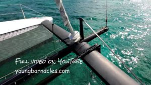
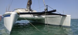
The Seagull Striker and Martingale form the critical backbone of a catamaran’s forward beam. This assembly strengthens the beam between the hulls and manages the substantial load from the forestay. On our Catana 42, Paikea, this is also the future attachment point for a storm sail, a key upgrade for our offshore ambitions.
While many designs attach the forestay directly to the beam, ours will attach to the longeron just behind the seagull striker, making the integrity of this entire structure non-negotiable.
The Engineering Rationale: Why Reinforce a “Strong Enough” Beam?
A valid question is why we’re adding a seagull striker and martingale to a beam that was theoretically strong enough. The answer lies in the difference between strength and stiffness.
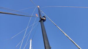
As Shayne explains, “The beam was strong enough in pure strength. However, the weakest link was the junction between the beam and the longeron. This discontinuity creates a focal point for high load. The amount of carbon needed to locally reinforce this junction would have been greater than the carbon used for the entire spreader and martingale assembly. By adding this truss, we end up with a stiffer beam and a lighter beam.”
This decision transforms a simple beam into a deep, lightweight truss, significantly improving handling and reducing energy-wasting flex.
The Process: Laminating the Structure & Making a Carbon Strap
The video above documents the initial phase: laminating the front beam to the longeron and installing the tip of a carbon fibre spreader as our seagull striker.
Fabricating the Unidirectional Carbon Strap:
The core of this upgrade was replacing the heavy 12mm stainless steel wire (over 5kg) with a solid carbon fibre strap (just over 1kg).
- Material Selection: We used 300g/m² unidirectional carbon fibre, where all the fibres run in one direction to maximize strength along the strap’s length.
- Press-Molding Technique: Instead of vacuum bagging, we used a clamped, press-molded assembly. We laid up 20 layers, resulting in a final thickness of ~6mm, and used an aluminum frame and clamps to consolidate the laminate. This method is highly effective for creating straight, void-free sections.
- Post-Processing & Fit: After curing, the strap was trimmed and the edges radiused to prevent stress concentrations. The final step involves slotting the beam to feed the carbon strap through, bonding it at the top and bottom to efficiently transfer loads into the hulls.
Further Reading on the Project Paikea Refit
To understand the full context of this front beam project, see the whole process:
- The Carbon Fiber Longeron & America’s Cup Rig: Dual Upgrades That Transformed Our Catamaran
 Author: Shayne and Anna Key Topic: While our salvaged America’s Cup rotating rig was a monumental upgrade, the custom carbon fiber longeron stands as its crucial counterpart, fundamentally changing how we… Read more: The Carbon Fiber Longeron & America’s Cup Rig: Dual Upgrades That Transformed Our Catamaran
 - Carbon Fiber vs. Aluminum Beam: A Catamaran Structural Upgrade
 Topic: We replaced our Catamaran 42’s original aluminum front beam with a custom carbon fiber beam and longeron. This wasn’t just a simple material swap; it was a complete structural… Read more: Carbon Fiber vs. Aluminum Beam: A Catamaran Structural Upgrade
 - Real-World Test: How Our New Carbon Front Beam Handled a Choppy SeaAuthor: Shayne and Anna Key Message: This sea trial proved that true performance isn’t just about strength or weight savings, but about how upgrades transform the sailing experience in real-world… Read more: Real-World Test: How Our New Carbon Front Beam Handled a Choppy Sea
- From America’s Cup to Our Catamaran: Rescuing a Carbon LegendAuthor: Shayne and Anna Key Message: The centerpiece of our rig is a mast with a legendary past: Rig #12 from Team New Zealand’s 2000 America’s Cup campaign. Rescued from a Valencia scrapyard… Read more: From America’s Cup to Our Catamaran: Rescuing a Carbon Legend
- Why We Chose Dyneema for Our Catamaran Trampoline (And How to Install It)Author: Shayne and Anna After completing our major carbon fiber front beam transformation, the final piece was installing a trampoline worthy of the upgrade. We chose Dyneema netting—the same high-performance material… Read more: Why We Chose Dyneema for Our Catamaran Trampoline (And How to Install It)